TOCATL Hexapod — ROS 2 + MuJoCo Walking Simulator
Project Overview
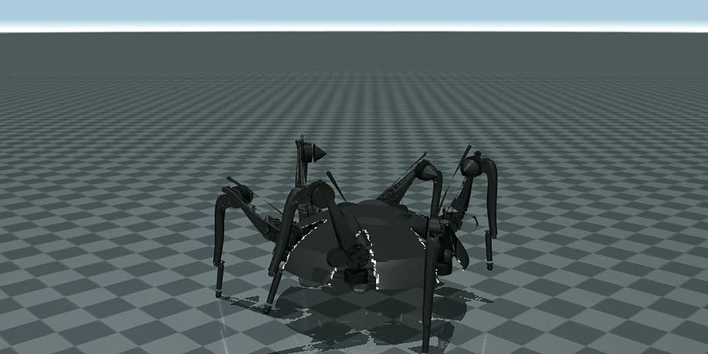
TOCATL mid-stride in MuJoCo, from the tracking camera used for the recorded walk. The body is the converted SolidWorks shell with the parametrically rebuilt 6-petal dome; the stylized cylinders at each hip are the CyberGear actuators.
The real TOCATL is driven by a console controller over CAN, with 18 Xiaomi CyberGear quasi-direct-drive actuators across six identical three-joint legs. The goal of this project was to reconstruct that whole locomotion pipeline in simulation — geometry, gait math, joint map, and control scheme — so that walking behaviour can be developed, tested, and recorded without touching hardware, and so the same gait node can later retarget the real CAN backend without changing any locomotion logic.
Everything is derived from the existing repository's pure-math modules rather than
re-derived: link lengths, forward and inverse kinematics, and joint-to-motor transforms
come from legacy_geometry.py; gait phase offsets, duty factors, and the
walking envelope come from legacy_reference.py; and the canonical
18-motor ordering comes from motor_map.py. The legacy deployment scripts
were read only as reference — never executed, since they enable real motors on startup.
Status — Built and Walking
All 7 acceptance tests pass headless in 1.4 s
The simulator is complete, walks firmly, renders the real CAD body, and is committed on
the branch codex/tocatl-mujoco-sim.
Acceptance test suite (test/test_walk.py)
| Test | Result |
|---|---|
| FK/IK round-trip over a grid of reachable foot points | Pass |
Model-FK identity (MJCF vs. legacy_geometry) |
Pass — agreement below 1 μm |
| 10 s static stand | Pass — height stable, no slip |
| 5 s tripod walk | Pass — 0.36 m, ≤2% speed error, roll/pitch < 0.8°, height σ 6 mm |
| Ripple gait | Pass |
| Wave gait | Pass |
| Mid-walk gait switch | Pass — no stumble |
Two tunings mattered more than the rest. Raising the stance stiffness ramp rate
(kp_rate_up) from 1 to 25 is what makes the legs plant rather
than settle, which is the entire difference between a firm-looking walk and a mushy
one. And the slip metric had to be measured during genuinely loaded contact
rather than over the whole stance phase mask — otherwise the number reports foot
motion from moments when the foot is not carrying weight at all.
The Robot
TOCATL is a radially symmetric hexapod: a central body carrying six identical legs, each with three revolute joints — hip yaw about the leg-local Z axis (swings the leg around its mount), hip pitch about the leg-local Y axis (lifts the thigh), and knee about the leg-local Y axis (bends the shin relative to the thigh). Eighteen joints in total, one CyberGear actuator each.
Link geometry
| Symbol | Meaning | Value |
|---|---|---|
d1 | Vertical drop from the yaw axis to the pitch axis | 114.25 mm |
d2 | Radial offset from the yaw axis to the pitch axis | 45.5561 mm |
d3 | Thigh (hip pitch → knee) | 330.3455 mm |
d4 | Shin (knee → foot tip) | 458.0 mm |
Maximum radial reach from the hip is d2 + d3 + d4 ≈ 834 mm, though the
practical planted reach stays well inside that. The body is modelled as a 600 mm
diameter disc, and leg k is mounted at 30° + k·60°, so the six
hips sit every 60° with each hip-yaw axis pointing radially outward.
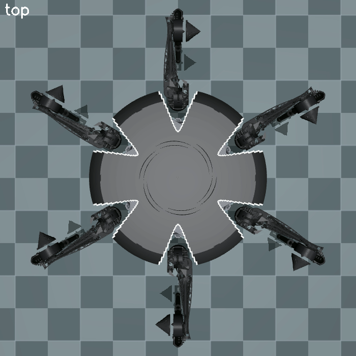
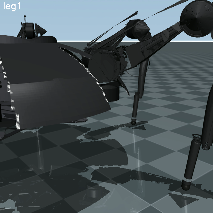
Left: the top-down camera, showing the six-fold radial symmetry — one leg every 60° around the 600 mm body disc, with the dome's petal creases and arched leg openings visible. Right: the per-leg camera, looking along leg 1 at the hip turret actuator, the thigh, and the shin running down to the foot sphere.
Kinematics
Inverse kinematics takes θ1 = atan2(y, x) and then solves the planar
two-link problem in the radial–vertical plane for θ2 and θ3
with the law of cosines, taking the positive-knee branch.
The single most important kinematic detail: the legacy FK rotates hip yaw about
[d2, 0, d1] rather than about the mount point. The MJCF reproduces this
exactly — verified to under a micrometre — which is why IK targets track with zero
error instead of accumulating a constant offset that would only show up later as
mysterious foot drift.
Joint and motor map
Motor IDs follow leg·10 + joint, where joint 1 is hip yaw, 2 is hip pitch,
and 3 is knee: leg 1 is 11/12/13, leg 2 is 21/22/23, and so on through leg 6 at
61/62/63. This exact ordering is preserved in every 18-element joint vector so the sim
maps one-to-one onto the real robot later. The real robot splits these across two CAN
buses; in simulation that split is irrelevant and survives only in metadata comments.
Actuator model — CyberGear MIT mode
The real command streamer sends MIT-style tuples (position, velocity, kp, kd, torque) per motor and the motor closes the loop internally. Rather than use MuJoCo position actuators, the sim uses pure torque actuators and computes τ in software from the incoming command. That choice is what preserves the real controller's per-joint, per-phase gain scheduling — with position actuators the gain schedule simply cannot be expressed. Torque is clipped to the CyberGear peak of ±12 N·m, and the legacy hip-pitch support-torque cap of 9.25 N·m serves as a useful sanity bound.
Gait Generation
A single global phase u ∈ [0, 1) advances at du = dt / cycle_time.
Each leg reads its own phase u_i = (u + phase_offset[i]) mod 1; if
u_i < duty_factor the leg is in stance with progress
s = u_i / duty, otherwise it is in swing with
s = (u_i − duty) / (1 − duty).
| Gait | Duty | Phase offsets (legs 0–5) | Character |
|---|---|---|---|
| Tripod | 0.5 | 0, ½, 0, ½, 0, ½ | Three legs swing at once — default, fastest |
| Ripple | 2/3 | 0, ⅓, ⅔, 0, ⅓, ⅔ | Two legs swing — smoother |
| Wave | 5/6 | ⅚, ⅓, ⅔, ⅙, ½, 0 | One leg swings — slowest, most stable |
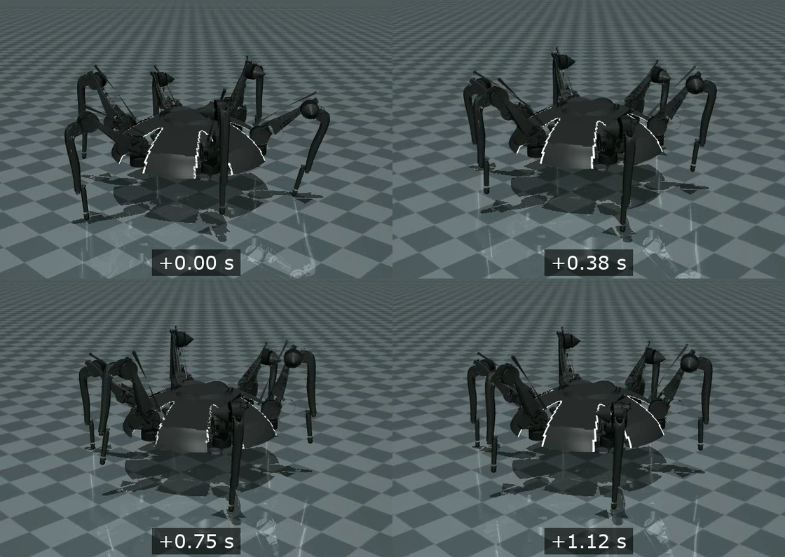
Four frames from the recorded tripod walk, sampled 0.375 s apart — a quarter of the nominal 1.5 s cycle time. The support pattern shifts from frame to frame as legs hand off between stance and swing, while the body height and attitude stay essentially constant throughout, which is what the walk is tuned for.
Foot trajectory
Each leg gets a neutral foot point radially out from its hip at R_foot, on
the ground plane, with the body at height H_body. Travel direction and
stride length come from the commanded body velocity, clamped to the stride maximum; a
yaw command adds a tangential per-leg component.
- Stance — the foot moves linearly from
+L/2to−L/2along the travel direction atz = 0. In world coordinates the foot stays put while the body advances, which is precisely the no-slip condition. - Swing — the foot returns from
−L/2to+L/2, lifting alongz = step_height · sin(π·s)for a clean arch.
Each foot target is then converted from the body frame into the leg's local frame by
subtracting the hip mount position and rotating by
−(mount_angle + body_yaw), run through IK, and packed into the 18-vector.
Walking envelope
| Parameter | Default | Range / limit |
|---|---|---|
| Stride length | 175 mm | 20 – 400 mm |
| Step height | 215 mm | 0 – 400 mm |
| Cycle time | 1.5 s | 1.2 s fast / 4.5 s slow |
| Foot speed | — | max 400 mm/s |
| Body speed | — | max 140 mm/s |
| Body yaw rate | — | max 35 °/s |
| Command stream | 200 Hz | gait/command loop rate |
Phase-scheduled gains — the key to a firm walk
Stance legs must be stiff so they plant hard and carry weight; swing legs must be soft
so they do not fight the air. The schedule runs stance Kp ≈ 100 against
swing Kp ≈ 10 with Kd ≈ 3, ramping Kp up quickly on entering
stance and down slowly on entering swing. The gait node passes
(pos, vel, kp, kd) per joint to the sim node, which applies the MIT-mode
torque law above.
Software Architecture
All new code lives in a single new ament_python package,
src/tocatl_sim, leaving the existing control package and its safety state
machine, command limiter, and calibration completely untouched.
| Node | Rate | Responsibility |
|---|---|---|
mujoco_sim_node |
500 Hz | Loads the MJCF, applies MIT-mode torque, steps physics at dt = 0.002 s, publishes joint states and the free-body pose, renders the live passive viewer or an offscreen frame stream. |
gait_node |
200 Hz | The locomotion brain — phase engine, foot trajectories, IK, and gain scheduling. Holds a planted stand pose at zero velocity so the robot is rock-steady between moves. |
teleop_keyboard |
— | Non-blocking hold-to-move keyboard driver publishing velocity and gait parameters, with a live status line. |
record_walk |
— | Offscreen renderer writing walk.mp4 at a fixed frame rate for
reproducible recordings. |
Keeping the gait outside the physics node is deliberate: it mirrors the real
robot's node split of gait generator → command sender → motors, so the identical
gait_node can later drive real CAN through a different backend without
any change to locomotion logic. A launch file starts all three nodes, and a params
YAML exposes every tunable — masses, gains, envelope, timestep, and camera.
Keyboard map (replacing the Xbox controller)
| Key | Action | Original pad input |
|---|---|---|
| W / S | Walk forward / backward | Left stick Y |
| A / D | Strafe left / right | Left stick X |
| Q / E | Turn left / right | Right stick X |
| 1 / 2 / 3 | Select tripod / ripple / wave | Gait select |
| [ / ] | Stride length − / + | D-pad X |
| - / = | Step height − / + | D-pad Y |
| R / F | Body height up / down | A / B |
| T / G | Leg radius out / in | Y / X |
| Space | Stop → graceful stand | LB (graceful return) |
| Z | Park (lower and settle) | RB |
| X / Esc | Quit cleanly | Back (E-stop) |
Commanded speeds slew toward their target rather than stepping to it, so motion reads smoothly on camera, and hold-to-move is used because it looks far better in a recording than press-to-set-velocity.
The MuJoCo Model
The MJCF is generated parametrically by a small Python builder that loops over the six
legs using the mount angles, so geometry can never drift out of sync between legs. No
CAD meshes are required for the dynamics: the base is a disc plate of radius 0.30 m
with a free joint, and each leg is a coxa capsule for the d2 offset, a
femur capsule of length 0.330 m, and a tibia capsule of length 0.458 m, ending in a
small high-friction foot sphere.
- Contacts — feet use
condim=6withfriction="1.2 0.02 0.001"plus a little solref/solimp softness so contacts do not jitter. - Actuators — one torque motor per hinge with
forcerange="-12 12". - Mass — roughly 13.6 kg total, with link mass placed near the joints since the CyberGear actuators dominate it, keeping the centre of mass low and central.
- Foot radius — 12 mm.
- Sensors — frame position and quaternion on the base, joint position and velocity on every hinge, and a touch sensor per foot, which is what makes the headless acceptance test possible.
CAD visuals
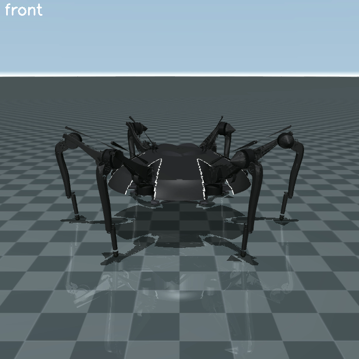
The front camera, showing the stance rematched to a photo of the real robot — body at 220 mm, a 0.59 m foot ring, and knees riding above the dome.
To make the sim look like the actual robot, 17 SolidWorks parts were converted to STL
entirely in-browser through a WASM converter, so the CAD never left the machine. The
lofted shell parts tessellate empty, so the six-petal dome was instead rebuilt
parametrically in a dome_builder.py script — creases, arched leg openings,
and a light trim — and junk disc and cone artifacts in some exports were removed by
connected-component filtering. The motors are stylized Ø86 × 36.5 mm cylinders.
Placement lives in a cad_layout.py module, with the hip turret transform
derived by cylinder-fitting its motor bore. The stance was rematched to a photo of the
real robot: body at 220 mm, a 0.59 m foot ring, knees riding above the dome. Setting
impratio=10 kills the foot creep that a sprawled stance otherwise
produces. Critically, all mesh geoms are massless, so the dynamics are
bit-identical to the capsule model and a single launch argument reverts to capsules.
Bring-Up and Debugging Ladder
Rather than build the whole thing and hope, the sim was brought up one rung at a time, each rung fixed before advancing, with the headless acceptance test asserting the metrics so tuning could iterate automatically before ever opening the viewer.
- Static stand — hold the stand pose for 10 s within 10 mm of height, roll and pitch under 2°, no slip. Sagging points at stance Kp, total mass or CoM height, an IK sign error bending the knees the wrong way, or feet that do not actually reach the ground at the commanded body height.
- March in place — tripod at zero stride. Buzzing points at contact softness, timestep, swing Kp, or missing joint damping.
- Slow tripod forward — the body should advance smoothly with stance feet fixed in world. Skating points at foot friction, stance Kp, a stance trajectory that is not moving the foot backward at exactly body speed, or fewer than three feet genuinely loaded.
- Faster and turning — raise velocity, add yaw, exercise ripple and wave, and switch gaits mid-walk without a stumble.
- Camera pass — run the recorder and tune out any wobble, toe drag, or hip pop. This is the real bar: it has to look firm and neat.
The acceptance thresholds encoded in the test are a forward displacement of at least 0.15 m and within 25% of commanded, mean roll and pitch under 3°, base-height standard deviation under 15 mm, no base–ground contact, no joint NaNs, and per-foot horizontal slip under 15 mm during that foot's stance phase.
Hardware-Safety Constraints
- No import of
can, the CyberGear driver,python-cybergear, orsocketcananywhere in the package. - No call to CAN setup, motor enable, or zero-position routines.
- The
legacy/tree is read-only reference. The legacy walking scripts were read to understand the gait, and the math was ported — the files were never executed. - Only the hardware-free pure-math modules are imported, never copied, so the sim and the real controller cannot drift apart.
- The software-safety CI passes locally on the branch.
Running It
Focus the MuJoCo window and drive with the keyboard map above. To record a run
headlessly, launch the offscreen recorder with the EGL rendering backend and it writes
walk.mp4 directly. The environment is Ubuntu 24.04 with ROS 2 Jazzy;
MuJoCo, NumPy, and SciPy come from pip, and the venv needs system site packages so
mujoco and rclpy are importable together.
Self-Study Curriculum
Alongside the build, I set myself a structured curriculum covering every concept the simulator depends on, with the standard for each topic being that I can explain the full locomotion pipeline unaided — motivation, the alternatives and why this approach wins, the mathematical intuition with every variable accounted for, its role in this project, the engineering trade-offs, and its failure modes.
- Coordinate frames and forward kinematics
- Inverse kinematics — two-link planar and the law of cosines
- Body reference frame and body→leg coordinate transforms
- Gait generation and the phase engine (duty factor, phase offsets)
- Tripod, ripple, and wave gaits, and static stability
- Foot trajectories (stance anchor, swing arch) and the no-slip condition
- CyberGear MIT control law — impedance / PD plus feedforward
- Phase-scheduled gains — stiff stance, soft swing
- MuJoCo modeling — MJCF, capsules, contacts, solref/solimp, impratio
- Contact and friction modeling
- ROS 2 architecture — node split, topics, loop rates
- FK validation and sim-to-real kinematic consistency
Open Items & Future Work
- Push the simulation branch and open the draft pull request (software-safety CI already passes locally).
- The knee bar is currently fixed to the femur rather than modelled as the real articulating four-bar linkage.
- The RoMeLa logo is not yet on the dome.
- Exact-CAD shell petals, if the body shell can be exported from SolidWorks in a form that tessellates.
- Sim-to-real: the joint ordering, control law, and gait math were all built to
transfer, so the natural next step is retargeting
gait_nodeto the real CAN backend behind the same topic contract.